I am going to work through this demonstration using a model of a toothpaste dispenser, which can be seen in the image below.
I shall do the demonstration in 3 steps, this first step will be the setting up of the model in Solidworks to make the necessary section cuts, and the creation of a separate configuration to show the actuator in a pressed down position.
The model is going to be sectioned twice so that we can build up a layered view that gradually peers deeper into the inner workings of the model.

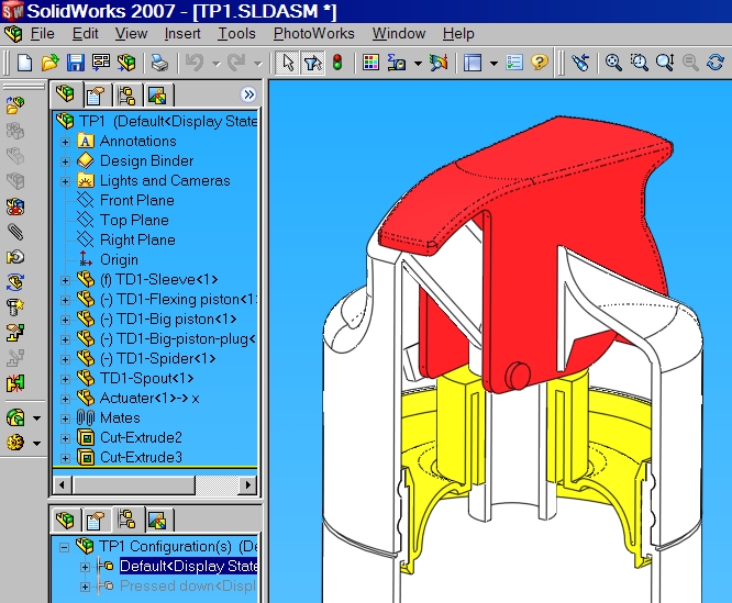
This view shows the model loaded into Solidworks and ready for the first section cut to be made.
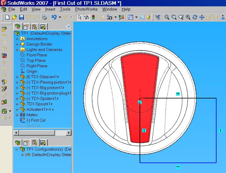
The cut shown above will be a straight rectangular cut with the top left corner on the centre line .
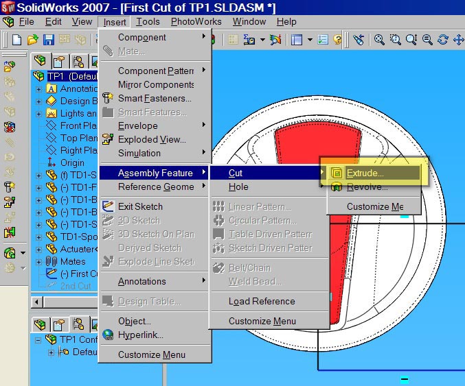
Having sketched the cut then find the Extrude cut tool in the pull down menu as shown above , click on this to reveal the preview shown below.
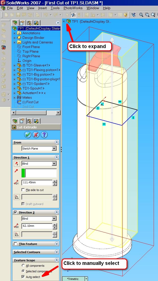
Grab the ends of the arrows to extend the yellow preview cut box both up and down to the full extent of the cut required. Now click on the Auto select arrow to deselect it, and then on the assembly component symbol indicated above to open the parts tree .
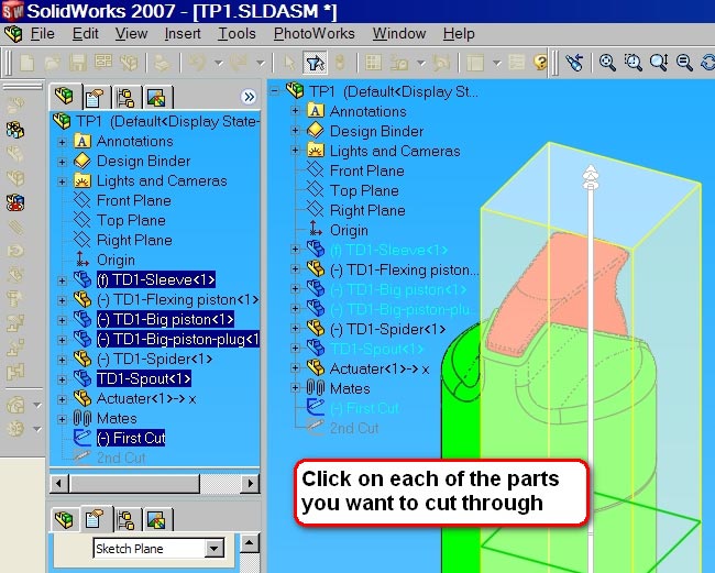

Clicking OK makes the cuts only through the parts that were designated to give you the finish shown above.
NB! The actual parts themselves have not been cu, only their representations in the assembly.
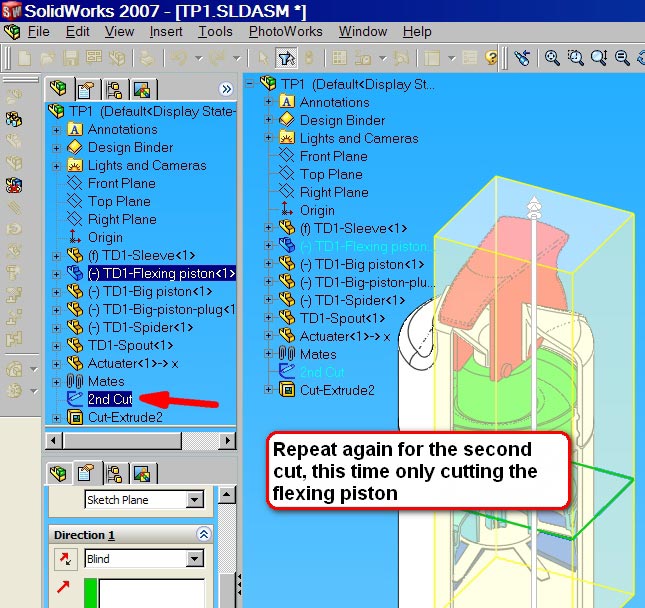
The second cut uses the same sketch as the first, we have only split the cutting operation so that separate states can be used later for rendering.
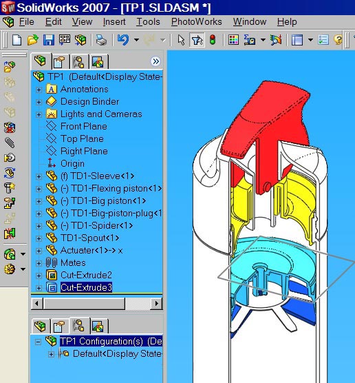
That’s all the cuts we need to do and these can be now used sequentially for rendering at the next stage.
Before we move onto that we need to create another configuration to show the actuator, the red lever at the top, pressed down fully showing deflecting the flexing piston.
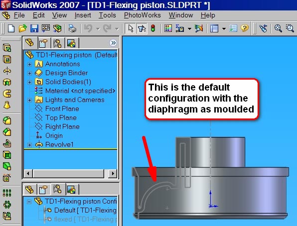
To be able to do this there needs to be a second configuration for the Flexing diaphragm as well, the too configurations for that are shown below
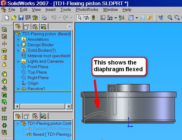
Using the above Flexing piston configuarations we can then create the two configurations for the Actuator, and these are shown below.

We have now completed all of the basic work in Solidworks to create are multi-layered renders at the next stage.


That is a great effect. do you find that the assembly cuts slow down the models? maybe it’s not to big to make a difference. Really cool, looking forward to the next one.
I have never noticed a slowing down , but I can’t say that I have looked for it, as most of my work tends to have these cuts in on the assembly from the get go.
Why did you not just use a section view?
A section view would cut thhrough all of the components and I wanted to leave some components whole so that they project forwards from the section. In this way more information can be conveyred from a single view.